

件电路图

查看电路图可知,当输出高电平时候LED灭,输出低电平时LED亮。
GPIO输出方式:推挽输出。
LED0是连接GPIO_B中的第5个引脚。
LED1是连接GPIO_E中的第5个引脚。
库函数介绍
头文件:stm32f10x_gpio.h
源文件:stm32f10x_gpio.c
跑马灯实验:
打开跑马灯实验的程序代码(官网光盘有提供)
FWLIB:misc.c、stm32f10x_gpio.c、stm32f10x_rcc.c(该文件涉及时钟)这三个文件属于不可缺少文件
HARDWARE:led.c(led初始化相关代码)
gpio.h(在gpio.c下面的文件):里面上面定义了一些宏定义,下面就是关于gpio的相关函数
void GPIO_DeInit(GPIO_TypeDef* GPIOx);
void GPIO_AFIODeInit(void);
void GPIO_Init(GPIO_TypeDef* GPIOx, GPIO_InitTypeDef* GPIO_InitStruct);//初始化
//输出模式进行设置(初始化),是对寄存器CRL、BRR、寄存器ODR。控制上下拉的
void GPIO_StructInit(GPIO_InitTypeDef* GPIO_InitStruct);

uint8_t GPIO_ReadInputDataBit(GPIO_TypeDef* GPIOx, uint16_t GPIO_Pin);//2个读取输入电平函数
uint16_t GPIO_ReadInputData(GPIO_TypeDef* GPIOx);//2个读取输入电平函数

uint8_t GPIO_ReadOutputDataBit(GPIO_TypeDef* GPIOx, uint16_t GPIO_Pin);//2个读取输出电平函数
uint16_t GPIO_ReadOutputData(GPIO_TypeDef* GPIOx);//2个读取输出电平函数

void GPIO_SetBits(GPIO_TypeDef* GPIOx, uint16_t GPIO_Pin);//4个设置输出电平函数,设置输出高电平
void GPIO_ResetBits(GPIO_TypeDef* GPIOx, uint16_t GPIO_Pin);//4个设置输出电平函数,设置输出低电平
void GPIO_WriteBit(GPIO_TypeDef* GPIOx, uint16_t GPIO_Pin, BitAction BitVal);//4个设置输出电平函数
void GPIO_Write(GPIO_TypeDef* GPIOx, uint16_t PortVal);//4个设置输出电平函数

void GPIO_PinLockConfig(GPIO_TypeDef* GPIOx, uint16_t GPIO_Pin);
void GPIO_EventOutputConfig(uint8_t GPIO_PortSource, uint8_t GPIO_PinSource);
void GPIO_EventOutputCmd(FunctionalState NewState);
void GPIO_PinRemapConfig(uint32_t GPIO_Remap, FunctionalState NewState);
void GPIO_EXTILineConfig(uint8_t GPIO_PortSource, uint8_t GPIO_PinSource);
void GPIO_ETH_MediaInterfaceConfig(uint32_t GPIO_ETH_MediaInterface);
若工程编译过,且魔术棒(options for target…)中选项卡“Output”中“Browse Information”选中,则可以查看对应函数的定义:(先编译,再选中想看的函数,右击,选择“Go To Definition Of XXX”),就可跳到对应该函数的定义位置
GPIO功能函数
1个初始化函数:
1、void GPIO_Init(GPIO_TypeDef* GPIOx, GPIO_InitTypeDef* GPIO_InitStruct);//初始化
/**
  * @brief  Initializes the GPIOx peripheral according to the specified
  *         parameters in the GPIO_InitStruct.
  * @param  GPIOx: where x can be (A..G) to select the GPIO peripheral.
  * @param  GPIO_InitStruct: pointer to a GPIO_InitTypeDef structure that
  *         contains the configuration information for the specified GPIO peripheral.
  * @retval None
  */
void GPIO_Init(GPIO_TypeDef* GPIOx, GPIO_InitTypeDef* GPIO_InitStruct)
{
  uint32_t currentmode = 0x00, currentpin = 0x00, pinpos = 0x00, pos = 0x00;
  uint32_t tmpreg = 0x00, pinmask = 0x00;
  /* Check the parameters */
  assert_param(IS_GPIO_ALL_PERIPH(GPIOx));
  assert_param(IS_GPIO_MODE(GPIO_InitStruct->GPIO_Mode));
  assert_param(IS_GPIO_PIN(GPIO_InitStruct->GPIO_Pin));

/*---------------------------- GPIO Mode Configuration -----------------------*/
  currentmode = ((uint32_t)GPIO_InitStruct->GPIO_Mode) & ((uint32_t)0x0F);
  if ((((uint32_t)GPIO_InitStruct->GPIO_Mode) & ((uint32_t)0x10)) != 0x00)
  {
    /* Check the parameters */
    assert_param(IS_GPIO_SPEED(GPIO_InitStruct->GPIO_Speed));
    /* Output mode */
    currentmode |= (uint32_t)GPIO_InitStruct->GPIO_Speed;
  }
/*---------------------------- GPIO CRL Configuration ------------------------*/
  /* Configure the eight low port pins */
  if (((uint32_t)GPIO_InitStruct->GPIO_Pin & ((uint32_t)0x00FF)) != 0x00)
  {
    tmpreg = GPIOx->CRL;
    for (pinpos = 0x00; pinpos < 0x08; pinpos++)
    {
      pos = ((uint32_t)0x01) << pinpos;
      /* Get the port pins position */
      currentpin = (GPIO_InitStruct->GPIO_Pin) & pos;
      if (currentpin == pos)
      {
        pos = pinpos << 2;
        /* Clear the corresponding low control register bits */
        pinmask = ((uint32_t)0x0F) << pos;
        tmpreg &= ~pinmask;
        /* Write the mode configuration in the corresponding bits */
        tmpreg |= (currentmode << pos);
        /* Reset the corresponding ODR bit */
        if (GPIO_InitStruct->GPIO_Mode == GPIO_Mode_IPD)
        {
          GPIOx->BRR = (((uint32_t)0x01) << pinpos);
        }
        else
        {
          /* Set the corresponding ODR bit */
          if (GPIO_InitStruct->GPIO_Mode == GPIO_Mode_IPU)
          {
            GPIOx->BSRR = (((uint32_t)0x01) << pinpos);
          }
        }
      }
    }
    GPIOx->CRL = tmpreg;
  }
/*---------------------------- GPIO CRH Configuration ------------------------*/
  /* Configure the eight high port pins */
  if (GPIO_InitStruct->GPIO_Pin > 0x00FF)
  {
    tmpreg = GPIOx->CRH;
    for (pinpos = 0x00; pinpos < 0x08; pinpos++)
    {
      pos = (((uint32_t)0x01) << (pinpos + 0x08));
      /* Get the port pins position */
      currentpin = ((GPIO_InitStruct->GPIO_Pin) & pos);
      if (currentpin == pos)
      {
        pos = pinpos << 2;
        /* Clear the corresponding high control register bits */
        pinmask = ((uint32_t)0x0F) << pos;
        tmpreg &= ~pinmask;
        /* Write the mode configuration in the corresponding bits */
        tmpreg |= (currentmode << pos);
        /* Reset the corresponding ODR bit */
        if (GPIO_InitStruct->GPIO_Mode == GPIO_Mode_IPD)
        {
          GPIOx->BRR = (((uint32_t)0x01) << (pinpos + 0x08));
        }
        /* Set the corresponding ODR bit */
        if (GPIO_InitStruct->GPIO_Mode == GPIO_Mode_IPU)
        {
          GPIOx->BSRR = (((uint32_t)0x01) << (pinpos + 0x08));
        }
      }
    }
    GPIOx->CRH = tmpreg;
  }
}
两个参数:
参数1:GPIO_TypeDef的结构体指针
typedef struct//将七个寄存器组织在一起的一个数据类型
{
  __IO uint32_t CRL;
  __IO uint32_t CRH;
  __IO uint32_t IDR;
  __IO uint32_t ODR;
  __IO uint32_t BSRR;
  __IO uint32_t BRR;
  __IO uint32_t LCKR;
} GPIO_TypeDef;
结构体:
七个寄存器,配合下面宏定义,用来指定哪一组IO口
assert_param是对参数的有效性进行判断。
  assert_param(IS_GPIO_ALL_PERIPH(GPIOx));
  #define IS_GPIO_ALL_PERIPH(PERIPH) (((PERIPH) == GPIOA) || \
                                    ((PERIPH) == GPIOB) || \
                                    ((PERIPH) == GPIOC) || \
                                    ((PERIPH) == GPIOD) || \
                                    ((PERIPH) == GPIOE) || \
                                    ((PERIPH) == GPIOF) || \
                                    ((PERIPH) == GPIOG))
 /很明显这边规定了这边第一个参数是要填写GPIOA~GPIOG的参数
参数2:GPIO_InitTypeDef的结构体指针
typedef struct
{
  uint16_t GPIO_Pin;             /*!< Specifies the GPIO pins to be configured.
                                      This parameter can be any value of @ref GPIO_pins_define */
  GPIOSpeed_TypeDef GPIO_Speed;  /*!< Specifies the speed for the selected pins.
                                      This parameter can be a value of @ref GPIOSpeed_TypeDef */
  GPIOMode_TypeDef GPIO_Mode;    /*!< Specifies the operating mode for the selected pins.
                                      This parameter can be a value of @ref GPIOMode_TypeDef */
}GPIO_InitTypeDef;
/**
  * @brief  Output Maximum frequency selection
  */
typedef enum
{
  GPIO_Speed_10MHz = 1,
  GPIO_Speed_2MHz,
  GPIO_Speed_50MHz
}GPIOSpeed_TypeDef;
#define IS_GPIO_SPEED(SPEED) (((SPEED) == GPIO_Speed_10MHz) || ((SPEED) == GPIO_Speed_2MHz) || \
                              ((SPEED) == GPIO_Speed_50MHz))
/**
  * @brief  Configuration Mode enumeration
  */

typedef enum
{ GPIO_Mode_AIN = 0x0,
  GPIO_Mode_IN_FLOATING = 0x04,
  GPIO_Mode_IPD = 0x28,
  GPIO_Mode_IPU = 0x48,
  GPIO_Mode_Out_OD = 0x14,
  GPIO_Mode_Out_PP = 0x10,
  GPIO_Mode_AF_OD = 0x1C,
  GPIO_Mode_AF_PP = 0x18
}GPIOMode_TypeDef;

#define IS_GPIO_MODE(MODE) (((MODE) == GPIO_Mode_AIN) || ((MODE) == GPIO_Mode_IN_FLOATING) || \
                            ((MODE) == GPIO_Mode_IPD) || ((MODE) == GPIO_Mode_IPU) || \
                            ((MODE) == GPIO_Mode_Out_OD) || ((MODE) == GPIO_Mode_Out_PP) || \
                            ((MODE) == GPIO_Mode_AF_OD) || ((MODE) == GPIO_Mode_AF_PP))
结构体:
第一个参数用来指定哪一个IO口。
第二个参数用来指定速度。
第三个参数用来指定模式。
assert_param是对参数的有效性进行判断。
  assert_param(IS_GPIO_MODE(GPIO_InitStruct->GPIO_Mode));
  //模式的话就是上面那段程序
  assert_param(IS_GPIO_PIN(GPIO_InitStruct->GPIO_Pin));
  //引脚
  /**
  * @}
  */

/** @defgroup GPIO_Exported_Constants
  * @{
  */

/** @defgroup GPIO_pins_define
  * @{
  */

#define GPIO_Pin_0                 ((uint16_t)0x0001)  /*!< Pin 0 selected */
#define GPIO_Pin_1                 ((uint16_t)0x0002)  /*!< Pin 1 selected */
#define GPIO_Pin_2                 ((uint16_t)0x0004)  /*!< Pin 2 selected */
#define GPIO_Pin_3                 ((uint16_t)0x0008)  /*!< Pin 3 selected */
#define GPIO_Pin_4                 ((uint16_t)0x0010)  /*!< Pin 4 selected */
#define GPIO_Pin_5                 ((uint16_t)0x0020)  /*!< Pin 5 selected */
#define GPIO_Pin_6                 ((uint16_t)0x0040)  /*!< Pin 6 selected */
#define GPIO_Pin_7                 ((uint16_t)0x0080)  /*!< Pin 7 selected */
#define GPIO_Pin_8                 ((uint16_t)0x0100)  /*!< Pin 8 selected */
#define GPIO_Pin_9                 ((uint16_t)0x0200)  /*!< Pin 9 selected */
#define GPIO_Pin_10                ((uint16_t)0x0400)  /*!< Pin 10 selected */
#define GPIO_Pin_11                ((uint16_t)0x0800)  /*!< Pin 11 selected */
#define GPIO_Pin_12                ((uint16_t)0x1000)  /*!< Pin 12 selected */
#define GPIO_Pin_13                ((uint16_t)0x2000)  /*!< Pin 13 selected */
#define GPIO_Pin_14                ((uint16_t)0x4000)  /*!< Pin 14 selected */
#define GPIO_Pin_15                ((uint16_t)0x8000)  /*!< Pin 15 selected */
#define GPIO_Pin_All               ((uint16_t)0xFFFF)  /*!< All pins selected */

#define IS_GPIO_PIN(PIN) ((((PIN) & (uint16_t)0x00) == 0x00) && ((PIN) != (uint16_t)0x00))

#define IS_GET_GPIO_PIN(PIN) (((PIN) == GPIO_Pin_0) || \
                              ((PIN) == GPIO_Pin_1) || \
                              ((PIN) == GPIO_Pin_2) || \
                              ((PIN) == GPIO_Pin_3) || \
                              ((PIN) == GPIO_Pin_4) || \
                              ((PIN) == GPIO_Pin_5) || \
                              ((PIN) == GPIO_Pin_6) || \
                              ((PIN) == GPIO_Pin_7) || \
                              ((PIN) == GPIO_Pin_8) || \
                              ((PIN) == GPIO_Pin_9) || \
                              ((PIN) == GPIO_Pin_10) || \
                              ((PIN) == GPIO_Pin_11) || \
                              ((PIN) == GPIO_Pin_12) || \
                              ((PIN) == GPIO_Pin_13) || \
                              ((PIN) == GPIO_Pin_14) || \
                              ((PIN) == GPIO_Pin_15))
GPIO_Init函数初始化样例
 GPIO_InitTypeDef  GPIO_InitStructure;//定义结构体GPIO_InitTypeDef,下面三个是结构体变量的初始化

 GPIO_InitStructure.GPIO_Pin = GPIO_Pin_5; //LED0-->PB.5 端口配置
 GPIO_InitStructure.GPIO_Mode = GPIO_Mode_Out_PP;  //推挽输出
 GPIO_InitStructure.GPIO_Speed = GPIO_Speed_50MHz; //IO口速度为50MHz
 GPIO_Init(GPIOB, &GPIO_InitStructure);	 //根据设定参数初始化GPIOB.5
2个读取输入电平函数:
2、uint8_t GPIO_ReadInputDataBit(GPIO_TypeDef* GPIOx, uint16_t GPIO_Pin);
/**
  * @brief  Reads the specified input port pin.
  * @param  GPIOx: where x can be (A..G) to select the GPIO peripheral.
  * @param  GPIO_Pin:  specifies the port bit to read.
  *   This parameter can be GPIO_Pin_x where x can be (0..15).
  * @retval The input port pin value.
  */
uint8_t GPIO_ReadInputDataBit(GPIO_TypeDef* GPIOx, uint16_t GPIO_Pin)
{
  uint8_t bitstatus = 0x00;

  /* Check the parameters */
  assert_param(IS_GPIO_ALL_PERIPH(GPIOx));
  assert_param(IS_GET_GPIO_PIN(GPIO_Pin));

  if ((GPIOx->IDR & GPIO_Pin) != (uint32_t)Bit_RESET)
  {
    bitstatus = (uint8_t)Bit_SET;
  }
  else
  {
    bitstatus = (uint8_t)Bit_RESET;
  }
  return bitstatus;
}
作用:读取某个GPIO的输入电平。实际操作的是GPIOx_IDR寄存器。
例如:
GPIO_ReadInputDataBit(GPIOA, GPIO_Pin_5);//读取GPIOA.5的输入电平
3、uint16_t GPIO_ReadInputData(GPIO_TypeDef* GPIOx);
作用:读取某组GPIO的输入电平。实际操作的是GPIOx_IDR寄存器。
例如:
GPIO_ReadInputData(GPIOA);//读取GPIOA组中所有io口输入电平
/**
  * @brief  Reads the specified GPIO input data port.
  * @param  GPIOx: where x can be (A..G) to select the GPIO peripheral.
  * @retval GPIO input data port value.
  */
uint16_t GPIO_ReadInputData(GPIO_TypeDef* GPIOx)
{
  /* Check the parameters */
  assert_param(IS_GPIO_ALL_PERIPH(GPIOx));

  return ((uint16_t)GPIOx->IDR);
}
2个读取输出电平函数:
4、uint8_t GPIO_ReadOutputDataBit(GPIO_TypeDef* GPIOx, uint16_t GPIO_Pin);
作用:读取某个GPIO的输出电平。实际操作的是GPIO_ODR寄存器。
例如:
GPIO_ReadOutputDataBit(GPIOA, GPIO_Pin_5);//读取GPIOA.5的输出电平
5、uint16_t GPIO_ReadOutputData(GPIO_TypeDef* GPIOx);
作用:读取某组GPIO的输出电平。实际操作的是GPIO_ODR寄存器。
例如:
GPIO_ReadOutputData(GPIOA);//读取GPIOA组中所有io口输出电平
4个设置输出电平函数:
6、void GPIO_SetBits(GPIO_TypeDef* GPIOx, uint16_t GPIO_Pin);
作用:设置某个IO口输出为高电平(1)。实际操作BSRR寄存器
7、void GPIO_ResetBits(GPIO_TypeDef* GPIOx, uint16_t GPIO_Pin);
作用:设置某个IO口输出为低电平(0)。实际操作的BRR寄存器。
8、void GPIO_WriteBit(GPIO_TypeDef* GPIOx, uint16_t GPIO_Pin, BitAction BitVal);
不常用,也是用来设置IO口输出电平。
9、void GPIO_Write(GPIO_TypeDef* GPIOx, uint16_t PortVal);
不常用,也是用来设置IO口输出电平。
使能IO口时钟
不同IO组,调用的时钟使能函数不一样。
rcc.h(在rcc.c下面的文件):里面上面定义了一些宏定义,和一些关于rcc的相关函数.
找到该函数:void RCC_APB2PeriphClockCmd(uint32_t RCC_APB2Periph, FunctionalState NewState);
void RCC_APB2PeriphClockCmd(uint32_t RCC_APB2Periph, FunctionalState NewState);
void RCC_APB2PeriphClockCmd(uint32_t RCC_APB2Periph, FunctionalState NewState)
{
  /* Check the parameters */
  assert_param(IS_RCC_APB2_PERIPH(RCC_APB2Periph));
  assert_param(IS_FUNCTIONAL_STATE(NewState));
  if (NewState != DISABLE)
  {
    RCC->APB2ENR |= RCC_APB2Periph;
  }
  else
  {
    RCC->APB2ENR &= ~RCC_APB2Periph;
  }
}
第一个参数:
#define RCC_APB2Periph_AFIO              ((uint32_t)0x00000001)
#define RCC_APB2Periph_GPIOA             ((uint32_t)0x00000004)
#define RCC_APB2Periph_GPIOB             ((uint32_t)0x00000008)
#define RCC_APB2Periph_GPIOC             ((uint32_t)0x00000010)
#define RCC_APB2Periph_GPIOD             ((uint32_t)0x00000020)
#define RCC_APB2Periph_GPIOE             ((uint32_t)0x00000040)
#define RCC_APB2Periph_GPIOF             ((uint32_t)0x00000080)
#define RCC_APB2Periph_GPIOG             ((uint32_t)0x00000100)
#define RCC_APB2Periph_ADC1              ((uint32_t)0x00000200)
#define RCC_APB2Periph_ADC2              ((uint32_t)0x00000400)
#define RCC_APB2Periph_TIM1              ((uint32_t)0x00000800)
#define RCC_APB2Periph_SPI1              ((uint32_t)0x00001000)
#define RCC_APB2Periph_TIM8              ((uint32_t)0x00002000)
#define RCC_APB2Periph_USART1            ((uint32_t)0x00004000)
#define RCC_APB2Periph_ADC3              ((uint32_t)0x00008000)
#define RCC_APB2Periph_TIM15             ((uint32_t)0x00010000)
#define RCC_APB2Periph_TIM16             ((uint32_t)0x00020000)
#define RCC_APB2Periph_TIM17             ((uint32_t)0x00040000)
#define RCC_APB2Periph_TIM9              ((uint32_t)0x00080000)
#define RCC_APB2Periph_TIM10             ((uint32_t)0x00100000)
#define RCC_APB2Periph_TIM11             ((uint32_t)0x00200000)

#define IS_RCC_APB2_PERIPH(PERIPH) ((((PERIPH) & 0xFFC00002) == 0x00) && ((PERIPH) != 0x00))
第二个参数:ENABLE、DISABLE
typedef enum {DISABLE = 0, ENABLE = !DISABLE} FunctionalState;
#define IS_FUNCTIONAL_STATE(STATE) (((STATE) == DISABLE) || ((STATE) == ENABLE))
添加SYSTEM文件夹
了解了最基础的gpio相关函数和rcc函数后,我们正式在学习篇1——新建库函数模版下开始写.
步骤一:添加SYSTEM文件夹到Tempalte文件夹中
在正点原子官网上下载的源代码中(库函数版本),随便找一个项目中复制文件夹SYSTEM,里面包含了最基础的三个函数:delay、sys、usart三个文件夹(这是最经常用的三个功能函数)。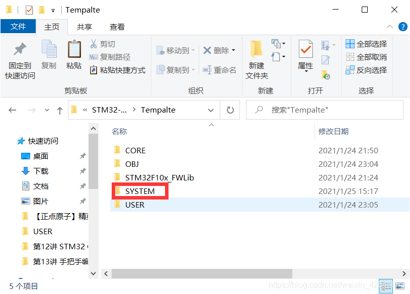
步骤二:在项目工程中添加SYSTEM文件夹
复制好后,在项目中添加SYSTEM文件夹。
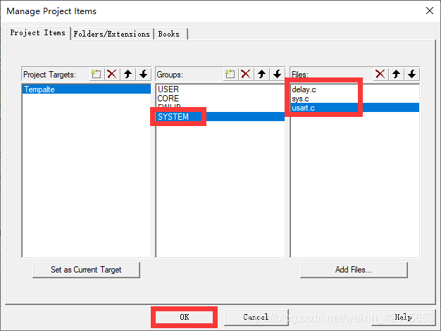
右击Projectc窗口下的“Target1”——“Manage Project Item”。
并在菜单栏“Manage Project items”中的“Groups”分组下添加“SYSTEM”文件件,并选中“SYSTEM”文件夹,点击“Add Files…”,找到“SYSTEM”目录下,添加三个文件:delay.c、sys.c、usart.c
步骤三:为SYSTEM文件夹下的头文件添加路径。
编译会发现找不到文件,这是还没有添加头文件路径。
选择魔术棒(Options for Target…)——选项卡“C/C++”——点击“Include Paths”右侧的按钮“…”——在点击“New”或者双击——点击按钮“…”选择以下三个路径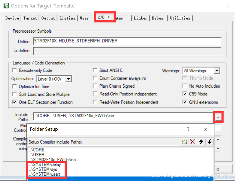
步骤四:创建HAREWARE文件夹到Tempalte文件夹中
创建HAREWARE文件夹到Tempalte文件夹中,并在Tempalte文件夹下载创建子文件夹LED(一个外设创建一个文件夹,该文件夹会存放外设对应的.c和.h的文件)

步骤五:在项目工程中添加HAREWARE文件夹并创建对应的.c和.h文件
跟之前一样添加到项目工程中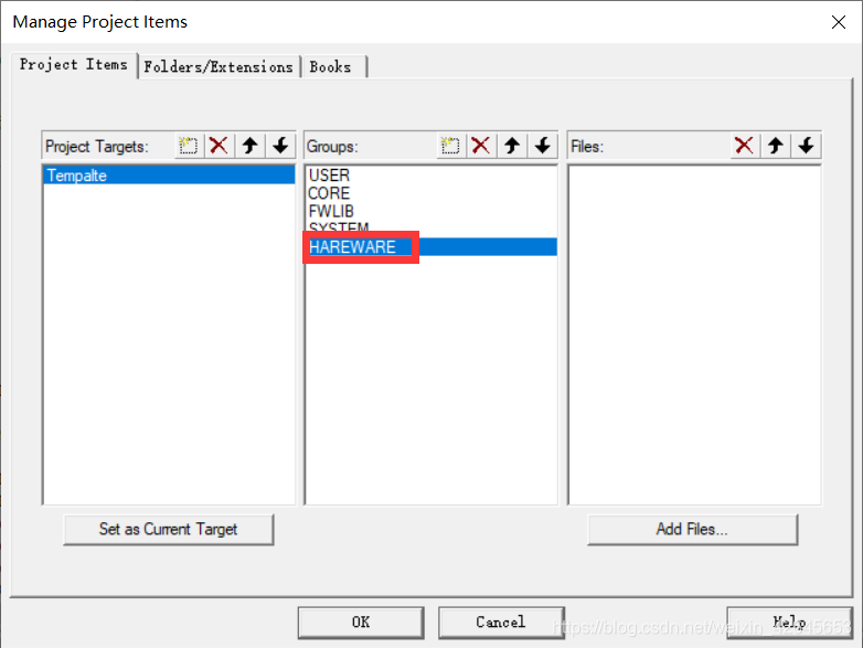
新建两个新的文件(还未保存和修改文件名及其文件后缀)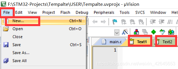
点击下图保存按键进行分别对两个文件进行保存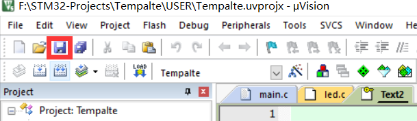
要把保存路径保存到刚刚创建的HARDWARE文件夹下的子文件夹LED文件夹,如下图所示: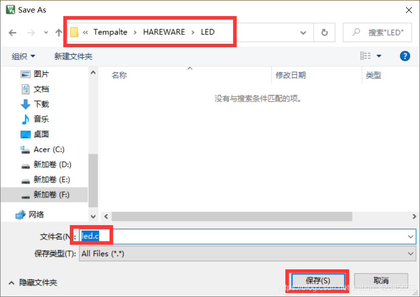
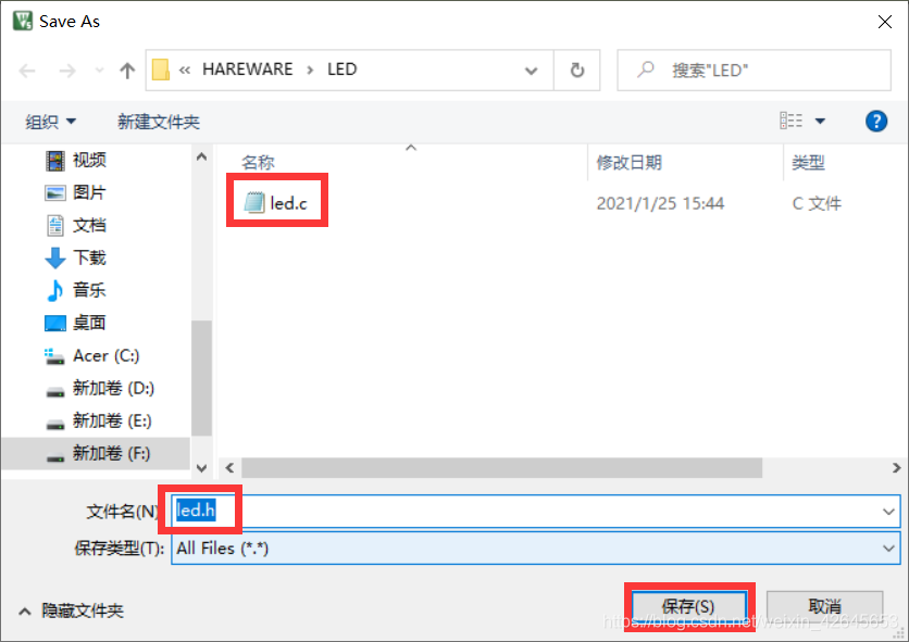
创建成功后就是下面这样的两个文件。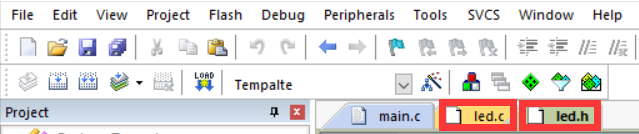
再把.c文件添加到HARDWARE文件夹的工程目录下。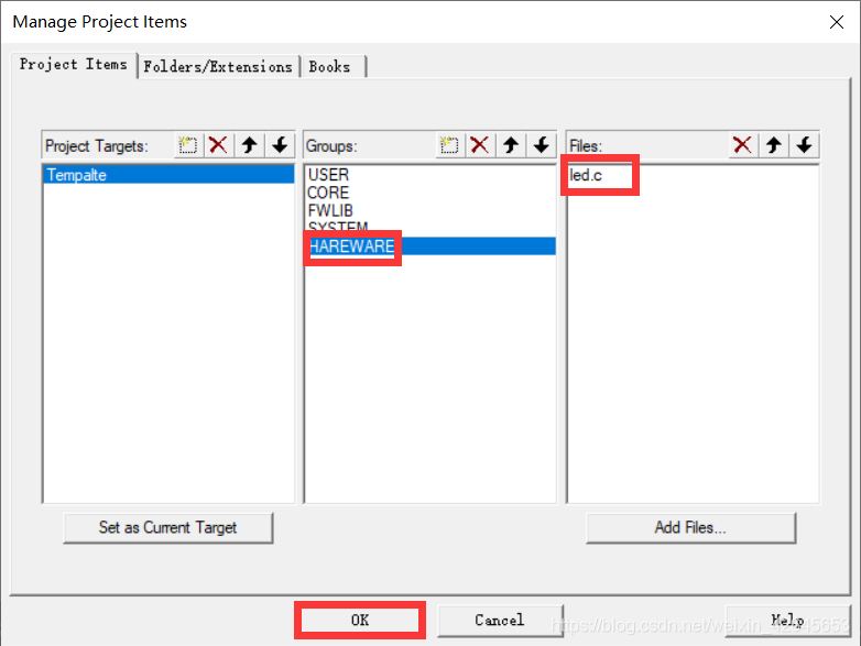
并把.h路径添加到软件下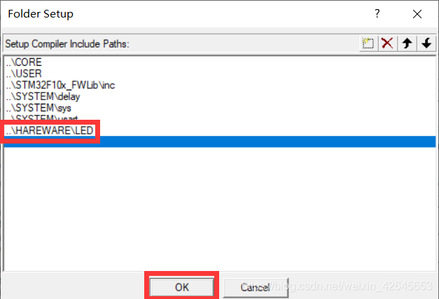
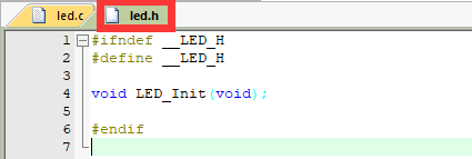
步骤六:编辑.h和.c文件
提示:头文件中,使用#ifndef #define #endif条件编译,避免头文件内容重复定义。
然后编译一下,发现文件没有报错,那么就没有任何问题,就需要在这个基础上再进一步的进行修改。
第一步:对时钟进行初始化,那么我们就要在工程中找到文件夹“FWLIB”——“stm32f10x_rcc.c”——“stm32f10x_rcc.h”中找到void RCC_APB2PeriphClockCmd(uint32_t RCC_APB2Periph, FunctionalState NewState);
后,先点击该函数后右击选择“Go To Difinition Of “xxx”",到达定义该函数处,在找到里面的两个assert_param检查参数的函数中,再分别“Go To Difinition Of “xxx”"来判断该函数的两个参数到底要填写什么。
注意:要使用该函数,需要在上面包含头文件:#include "stm32f10x.h"
即:
#include "led.h"
#include "stm32f10x.h"

void LED_Init(void){
	RCC_APB2PeriphClockCmd(RCC_APB2Periph_GPIOB, ENABLE);
	RCC_APB2PeriphClockCmd(RCC_APB2Periph_GPIOE, ENABLE);
	//以上两条实际可以直接用位或写成一行:RCC_APB2PeriphClockCmd(RCC_APB2Periph_GPIOB|RCC_APB2Periph_GPIOE, ENABLE);
}
第二步 初始化IO口模式,那么我们就要在工程中找到文件夹“FWLIB”——“stm32f10x_gpio.c”——“stm32f10x_gpio.h”中找到void GPIO_Init(GPIO_TypeDef* GPIOx, GPIO_InitTypeDef* GPIO_InitStruct);后,跟上面一样,要根据文件来填写里面参数要填写什么,第一个参数是比较简单的额,第二个参数是一个结构体变量,需要先定义一个结构体变量后,在分别填写结构体变量中的三个成员变量。并且第二个参数需要在变量前加上取址符。最后的程序为:
#include "led.h"
#include "stm32f10x.h"

void LED_Init(void){
	GPIO_InitTypeDef GPIO_InitStructure;
	RCC_APB2PeriphClockCmd(RCC_APB2Periph_GPIOB, ENABLE);
	RCC_APB2PeriphClockCmd(RCC_APB2Periph_GPIOE, ENABLE);
	//以上两条实际可以直接用位或写成一行:RCC_APB2PeriphClockCmd(RCC_APB2Periph_GPIOB|RCC_APB2Periph_GPIOE, ENABLE);

	GPIO_InitStructure.GPIO_Mode= GPIO_Mode_Out_PP;			//模式选择推挽输出
	GPIO_InitStructure.GPIO_Pin=GPIO_Pin_5;					//引脚选择5
	GPIO_InitStructure.GPIO_Speed=GPIO_Speed_50MHz;			//速度旋转50MHz
	GPIO_Init(GPIOB, &GPIO_InitStructure);
	//第一个参数GPIOB
	//第二个参数是一个结构体变量,要用&去取,且该结构体中有三个变量
	//要根据assert_param中去确定要填写什么样的格式数值。


	GPIO_InitStructure.GPIO_Mode= GPIO_Mode_Out_PP;			//模式选择推挽输出
	GPIO_InitStructure.GPIO_Pin=GPIO_Pin_5;					//引脚选择5
	GPIO_InitStructure.GPIO_Speed=GPIO_Speed_50MHz;			//速度旋转50MHz
	GPIO_Init(GPIOE, &GPIO_InitStructure);
	//第一个参数GPIOE
	//第二个参数是一个结构体变量,要用&去取,且该结构体中有三个变量
	//要根据assert_param中去确定要填写什么样的格式数值。


}
注意:现在编译程序是没有问题的,但可能会报错的是最后需要在程序的结束添加几行回车。
第三步 操作IO口,因为起初希望LED是灭的,所以要先设置输出高电平。那么我们就要在工程中找到文件夹“FWLIB”——“stm32f10x_gpio.c”——“stm32f10x_gpio.h”中找到void GPIO_SetBits(GPIO_TypeDef* GPIOx, uint16_t GPIO_Pin);后,根据上面同样的原理可知道改函数的两个参数应该填写什么,得到以下程序:
GPIO_SetBits(GPIOE, GPIO_Pin_5);第一个参数选择哪组,第二个参数选择哪个。
#include "led.h"
#include "stm32f10x.h"

void LED_Init(void){
	GPIO_InitTypeDef GPIO_InitStructure;
	RCC_APB2PeriphClockCmd(RCC_APB2Periph_GPIOB, ENABLE);
	RCC_APB2PeriphClockCmd(RCC_APB2Periph_GPIOE, ENABLE);
	//以上两条实际可以直接用位或写成一行:RCC_APB2PeriphClockCmd(RCC_APB2Periph_GPIOB|RCC_APB2Periph_GPIOE, ENABLE);

	GPIO_InitStructure.GPIO_Mode= GPIO_Mode_Out_PP;			//模式选择推挽输出
	GPIO_InitStructure.GPIO_Pin=GPIO_Pin_5;					//引脚选择5
	GPIO_InitStructure.GPIO_Speed=GPIO_Speed_50MHz;			//速度旋转50MHz
	GPIO_Init(GPIOB, &GPIO_InitStructure);
	//第一个参数GPIOB
	//第二个参数是一个结构体变量,要用&去取,且该结构体中有三个变量
	//要根据assert_param中去确定要填写什么样的格式数值。
	GPIO_SetBits(GPIOB, GPIO_Pin_5);

	GPIO_InitStructure.GPIO_Mode= GPIO_Mode_Out_PP;			//模式选择推挽输出
	GPIO_InitStructure.GPIO_Pin=GPIO_Pin_5;					//引脚选择5
	GPIO_InitStructure.GPIO_Speed=GPIO_Speed_50MHz;			//速度旋转50MHz
	GPIO_Init(GPIOE, &GPIO_InitStructure);
	//第一个参数GPIOE
	//第二个参数是一个结构体变量,要用&去取,且该结构体中有三个变量
	//要根据assert_param中去确定要填写什么样的格式数值。
	GPIO_SetBits(GPIOE, GPIO_Pin_5);

}
步骤七:编辑main.c文件
Project菜单栏下的Tempalte文件夹下USER文件夹下的main.c文件,修改为以下程序:实现两个LED同时闪烁的功能
#include "stm32f10x.h"			//stm32必要的头文件
#include "led.h"				//led的头文件
#include "delay.h"				//delay的头文件
int main(void){
	LED_Init();			//LED初始化函数
	delay_init();		//delay初始化函数
	while(1){
		GPIO_SetBits(GPIOB, GPIO_Pin_5);	//将GPIOB组中,引脚5,设置为高电平,LED灭
		GPIO_SetBits(GPIOE, GPIO_Pin_5);	//将GPIOE组中,引脚5,设置为高电平,LED灭
		delay_ms(500);						//延时500毫秒
		GPIO_ResetBits(GPIOB, GPIO_Pin_5);	//将GPIOB组中,引脚5,设置为低电平,LED亮
		GPIO_ResetBits(GPIOE, GPIO_Pin_5);	//将GPIOE组中,引脚5,设置为低电平,LED亮
		delay_ms(500);						//延时500毫秒
	}
}


评论(0)
您还未登录,请登录后发表或查看评论