

Python Jetson GPIO Src: https://pypi.org/project/Jetson.GPIO/
目录
NVIDIA:
Jetson TX1, TX2, AGX Xavier, and Nano development boards contain a 40 pin GPIO header, similar to the 40 pin header in the Raspberry Pi. These GPIOs can be controlled for digital input and output using the Python library provided in the Jetson GPIO Library package. The library has the same API as the RPi.GPIO library for Raspberry Pi in order to provide an easy way to move applications running on the Raspberry Pi to the Jetson board.
This document walks through what is contained in The Jetson GPIO library package, how to configure the system and run the provided sample applications, and the library API.
1. Jetson GPIO 安装
Using pip
The easiest way to install this library is using
pip:sudo pip install Jetson.GPIOManual download
You may clone this git repository, or download a copy of it as an archive file and decompress it. You may place the library files anywhere you like on your system. You may use the library directly from this directory by manually setting PYTHONPATH, or install it using setup.py:
sudo python3 setup.py installSetting User Permissions
In order to use the Jetson GPIO Library, the correct user permissions/groups must be set first.
Create a new gpio user group. Then add your user to the newly created group.
sudo groupadd -f -r gpio
sudo usermod -a -G gpio your_user_name
Install custom udev rules by copying the 99-gpio.rules file into the rules.d directory.
If you have downloaded the source to Jetson.GPIO:
sudo cp lib/python/Jetson/GPIO/99-gpio.rules /etc/udev/rules.d/If you installed Jetson.GPIO from a package, e.g. using pip into a virtual environment:
sudo cp venv/lib/pythonNN/site-packages/Jetson/GPIO/99-gpio.rules /etc/udev/rules.d/For the new rule to take place, you either need to reboot or reload the udev rules by running:
sudo udevadm control --reload-rules && sudo udevadm triggerRunning the sample scripts
With the permissions set as needed, the sample applications provided in the samples/ directory can be used. The following describes the operation of each application:
- simple_input.py: This application uses the BCM pin numbering mode and reads the value at pin 12 of the 40 pin header and prints the value to the screen.
- simple_out.py: This application uses the BCM pin numbering mode from Raspberry Pi and outputs alternating high and low values at BCM pin 18 (or board pin 12 on the header) every 2 seconds.
- button_led.py: This application uses the BOARD pin numbering. It requires a button connected to pin 18 and GND, a pull-up resistor connecting pin 18 to 3V3 and an LED and current limiting resistor connected to pin 12. The application reads the button state and keeps the LED on for 1 second every time the button is pressed.
- button_event.py: This application uses the BOARD pin numbering. It requires a button connected to pin 18 and GND, a pull-up resistor connecting the button to 3V3 and an LED and current limiting resistor connected to pin 12. The application performs the same function as the button_led.py but performs a blocking wait for the button press event instead of continuously checking the value of the pin in order to reduce CPU usage.
- button_interrupt.py: This application uses the BOARD pin numbering. It requires a button connected to pin 18 and GND, a pull-up resistor connecting the button to 3V3, an LED and current limiting resistor connected to pin 12 and a second LED and current limiting resistor connected to pin 13. The application slowly blinks the first LED continuously and rapidly blinks the second LED five times only when the button is pressed.
To run these sample applications if Jetson.GPIO is added to the PYTHONPATH:
python3 <name_of_application_to_run>Alternatively, if Jetson.GPIO is not added to the PYTHONPATH, the run_sample.sh script can be used to run these sample applications. This can be done with the following command when in the samples/ directory:
./run_sample.sh <name_of_application_to_run>The usage of the script can also be viewed by using:
./run_sample.sh -h
./run_sample.sh --help
Complete library API
The Jetson GPIO library provides all public APIs provided by the RPi.GPIO library. The following discusses the use of each API:
1. Importing the libary
To import the Jetson.GPIO module use:
import Jetson.GPIO as GPIOThis way, you can refer to the module as GPIO throughout the rest of the application. The module can also be imported using the name RPi.GPIO instead of Jetson.GPIO for existing code using the RPi library.
2. Pin numbering
The Jetson GPIO library provides four ways of numbering the I/O pins. The first two correspond to the modes provided by the RPi.GPIO library, i.e BOARD and BCM which refer to the pin number of the 40 pin GPIO header and the Broadcom SoC GPIO numbers respectively. The remaining two modes, CVM and TEGRA_SOC use strings instead of numbers which correspond to signal names on the CVM/CVB connector and the Tegra SoC respectively.
To specify which mode you are using (mandatory), use the following function call:
GPIO.setmode(GPIO.BOARD)
# or
GPIO.setmode(GPIO.BCM)
# or
GPIO.setmode(GPIO.CVM)
# or
GPIO.setmode(GPIO.TEGRA_SOC)
To check which mode has be set, you can call:
mode = GPIO.getmode()The mode must be one of GPIO.BOARD, GPIO.BCM, GPIO.CVM, GPIO.TEGRA_SOC or None.
3. Warnings
It is possible that the GPIO you are trying to use is already being used external to the current application. In such a condition, the Jetson GPIO library will warn you if the GPIO being used is configured to anything but the default direction (input). It will also warn you if you try cleaning up before setting up the mode and channels. To disable warnings, call:
GPIO.setwarnings(False)4. Set up a channel
The GPIO channel must be set up before use as input or output. To configure the channel as input, call:
# (where channel is based on the pin numbering mode discussed above)
GPIO.setup(channel, GPIO.IN)
To set up a channel as output, call:
GPIO.setup(channel, GPIO.OUT)It is also possible to specify an initial value for the output channel:
GPIO.setup(channel, GPIO.OUT, initial=GPIO.HIGH)When setting up a channel as output, it is also possible to set up more than one channel at once:
# add as many as channels as needed. You can also use tuples: (18,12,13)
channels = [18, 12, 13]
GPIO.setup(channels, GPIO.OUT)
5. Input
To read the value of a channel, use:
GPIO.input(channel)This will return either GPIO.LOW or GPIO.HIGH.
6. Output
To set the value of a pin configured as output, use:
GPIO.output(channel, state)where state can be GPIO.LOW or GPIO.HIGH.
You can also output to a list or tuple of channels:
channels = [18, 12, 13] # or use tuples
GPIO.output(channels, GPIO.HIGH) # or GPIO.LOW
# set first channel to HIGH and rest to LOW
GPIO.output(channel, (GPIO.LOW, GPIO.HIGH, GPIO.HIGH))
7. Clean upAt the end of the program, it is good to clean up the channels so that all pins are set in their default state. To clean up all channels used, call:
GPIO.cleanup()If you don't want to clean all channels, it is also possible to clean up individual channels or a list or tuple of channels:
GPIO.cleanup(chan1) # cleanup only chan1
GPIO.cleanup([chan1, chan2]) # cleanup only chan1 and chan2
GPIO.cleanup((chan1, chan2))  # does the same operation as previous statement
8. Jetson Board Information and library versionTo get information about the Jetson module, use/read:
GPIO.JETSON_INFOThis provides a Python dictionary with the following keys: P1_REVISION, RAM, REVISION, TYPE, MANUFACTURER and PROCESSOR. All values in the dictionary are strings with the exception of P1_REVISION which is an integer.
To get information about the library version, use/read:
GPIO.VERSIONThis provides a string with the X.Y.Z version format.
9. Interrupts
Aside from busy-polling, the library provides three additional ways of monitoring an input event:
THE WAIT_FOR_EDGE() FUNCTION
This function blocks the calling thread until the provided edge(s) is detected. The function can be called as follows:
GPIO.wait_for_edge(channel, GPIO.RISING)The second parameter specifies the edge to be detected and can be GPIO.RISING, GPIO.FALLING or GPIO.BOTH. If you only want to limit the wait to a specified amount of time, a timeout can be optionally set:
# timeout is in milliseconds
GPIO.wait_for_edge(channel, GPIO.RISING, timeout=500)
The function returns the channel for which the edge was detected or None if a timeout occurred.THE EVENT_DETECTED() FUNCTION
This function can be used to periodically check if an event occurred since the last call. The function can be set up and called as follows:
# set rising edge detection on the channel
GPIO.add_event_detect(channel, GPIO.RISING)
run_other_code()
if GPIO.event_detected(channel):
    do_something()
As before, you can detect events for GPIO.RISING, GPIO.FALLING or GPIO.BOTH.A CALLBACK FUNCTION RUN WHEN AN EDGE IS DETECTED
This feature can be used to run a second thread for callback functions. Hence, the callback function can be run concurrent to your main program in response to an edge. This feature can be used as follows:
# define callback function
def callback_fn(channel):
    print("Callback called from channel %s" % channel)

# add rising edge detection
GPIO.add_event_detect(channel, GPIO.RISING, callback=callback_fn)
More than one callback can also be added if required as follows:def callback_one(channel): print("First Callback") def callback_two(channel): print("Second Callback") GPIO.add_event_detect(channel, GPIO.RISING) GPIO.add_event_callback(channel, callback_one) GPIO.add_event_callback(channel, callback_two)
The two callbacks in this case are run sequentially, not concurrently since there is only thread running all callback functions.In order to prevent multiple calls to the callback functions by collapsing multiple events in to a single one, a debounce time can be optionally set:
# bouncetime set in milliseconds
GPIO.add_event_detect(channel, GPIO.RISING, callback=callback_fn,
bouncetime=200)
If the edge detection is not longer required it can be removed as follows:GPIO.remove_event_detect(channel)10. Check function of GPIO channels
This feature allows you to check the function of the provided GPIO channel:
GPIO.gpio_function(channel)The function returns either GPIO.IN or GPIO.OUT.
11. PWM
See samples/simple_pwm.py for details on how to use PWM channels.
The Jetson.GPIO library supports PWM only on pins with attached hardware PWM controllers. Unlike the RPi.GPIO library, the Jetson.GPIO library does not implement Software emulated PWM. Jetson Nano supports 2 PWM channels, and Jetson AGX Xavier supports 3 PWM channels. Jetson TX1 and TX2 do not support any PWM channels.
The system pinmux must be configured to connect the hardware PWM controlller(s) to the relevant pins. If the pinmux is not configured, PWM signals will not reach the pins! The Jetson.GPIO library does not dynamically modify the pinmux configuration to achieve this. Read the L4T documentation for details on how to configure the p
2. 设置GPIO模式
GPIO四种模式:BOARD、BCM、CVM和TEGRA_SOC 的不同
四种模式可以分为两组:BOARD和BCM一组,CVM和TEFRA_SOC一组。
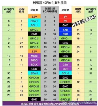
1.BOARD和BCM是来源于RPi.GPIO library,因此Jetson Nano的标识对照和树莓派一致,可参考树莓派对照表。
详情请参考文章:https://haowang.blog.csdn.net/article/details/119172263
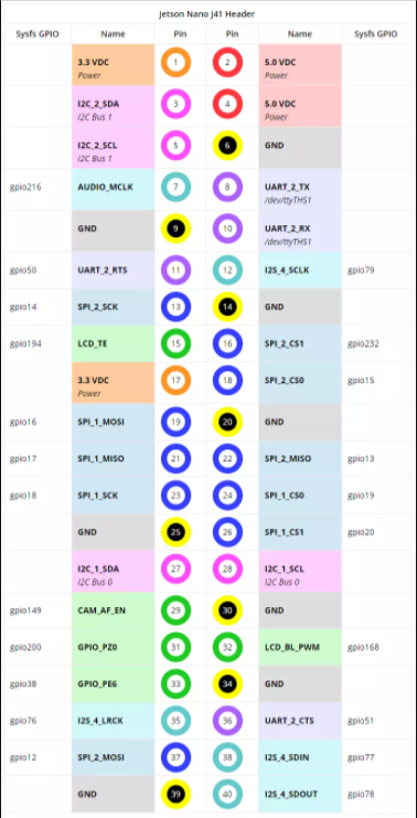
如下是Jetson正视管脚图。可见Jetson Nano中GPIO的各个管脚功能,具有Sysfs GPIO的管脚都可以作为通用输入输出管脚。其余管脚可以在name下面看到各自功能,具有通信功能的可看到查询地址或串口名称等信息。


评论(0)
您还未登录,请登录后发表或查看评论