

URDF 需要集成进 Rviz 或 Gazebo 才能显示可视化的机器人模型,前面已经介绍了URDF 与 Rviz 的集成,本节主要介绍:
- URDF 与 Gazebo 的基本集成流程
- 如果要在 Gazebo 中显示机器人模型,URDF 需要做的一些额外配置
- 关于Gazebo仿真环境的搭建
一、URDF与Gazebo基本集成流程
1、创建功能包
创建新功能包,导入依赖包: urdf、xacro、gazebo_ros、gazebo_ros_control、gazebo_plugins
2、编写URDF文件
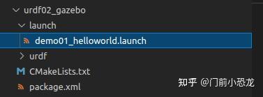
新建urdf ---> demo01_helloworld.urdf
<robot name="mycar">
    <link name="base_link">
        <visual>
            <geometry>
                <box size="0.5 0.3 0.1" />
            </geometry>
            <origin xyz="0.0 0.0 0.0" rpy="0.0 0.0 0.0" />
            <material name="yellow">
                <color rgba="0.5 0.3 0.0 1" />
            </material>
        </visual>
        <collision>
            <geometry>
                <box size="0.5 0.3 0.1" />
            </geometry>
            <origin xyz="0.0 0.0 0.0" rpy="0.0 0.0 0.0" />
        </collision>
        <inertial>
            <origin xyz="0 0 0" />
            <mass value="6" />
            <inertia ixx="1" ixy="0" ixz="0" iyy="0" iyz="1" izz="1" />
        </inertial>
    </link>
    <gazebo reference="base_link">
        <material>Gazebo/Red</material>
    </gazebo>

</robot>
注意, 当 URDF 需要与 Gazebo 集成时,和 Rviz 有明显区别:
1.必须使用 collision 标签,因为既然是仿真环境,那么必然涉及到碰撞检测,collision 提供碰撞检测的依据。
2.必须使用 inertial 标签,此标签标注了当前机器人某个刚体部分的惯性矩阵,用于一些力学相关的仿真计算。
3.颜色设置,也需要重新使用 gazebo 标签标注,因为之前的颜色设置为了方便调试包含透明度,仿真环境下没有此选项。
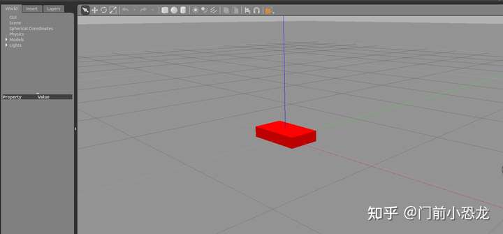
3、启动Gazebo并显示模型
launch 文件实现
<launch>

    <!-- 将 Urdf 文件的内容加载到参数服务器 -->
    <param name="robot_description" textfile="$(find urdf03_gazebo)/urdf/demo01_helloworld.urdf" />

    <!-- 启动 gazebo -->
    <include file="$(find gazebo_ros)/launch/empty_world.launch" />

    <!-- 在 gazebo 中显示机器人模型 -->
    <node pkg="gazebo_ros" type="spawn_model" name="model" args="-urdf -model mycar -param robot_description"  />
</launch>
备注:当gazebo因为异常情况退出时,输入:$ export SVGA_VGPU10=0
二、URDF集成Gazebo相关设置
1、collision
如果机器人link是标准的几何体形状,和link的 visual 属性设置一致即可。
2、inertial
惯性矩阵的设置需要结合link的质量与外形参数动态生成,标准的球体、圆柱与立方体的惯性矩阵公式如下(已经封装为 xacro 实现):
球体惯性矩阵
<!-- Macro for inertia matrix -->
    <xacro:macro name="sphere_inertial_matrix" params="m r">
        <inertial>
            <mass value="${m}" />
            <inertia ixx="${2*m*r*r/5}" ixy="0" ixz="0"
                iyy="${2*m*r*r/5}" iyz="0"
                izz="${2*m*r*r/5}" />
        </inertial>
    </xacro:macro>
圆柱惯性矩阵
<xacro:macro name="cylinder_inertial_matrix" params="m r h">
        <inertial>
            <mass value="${m}" />
            <inertia ixx="${m*(3*r*r+h*h)/12}" ixy = "0" ixz = "0"
                iyy="${m*(3*r*r+h*h)/12}" iyz = "0"
                izz="${m*r*r/2}" />
        </inertial>
    </xacro:macro>
立方体惯性矩阵
<xacro:macro name="Box_inertial_matrix" params="m l w h">
       <inertial>
               <mass value="${m}" />
               <inertia ixx="${m*(h*h + l*l)/12}" ixy = "0" ixz = "0"
                   iyy="${m*(w*w + l*l)/12}" iyz= "0"
                   izz="${m*(w*w + h*h)/12}" />
       </inertial>
   </xacro:macro>
需要注意的是,原则上,除了 base_footprint 外,机器人的每个刚体部分都需要设置惯性矩阵,且惯性矩阵必须经计算得出,如果随意定义刚体部分的惯性矩阵,那么可能会导致机器人在 Gazebo 中出现抖动,移动等现象。
3、颜色设置
在 gazebo 中显示 link 的颜色,必须要使用指定的标签:
<gazebo reference="link节点名称">
     <material>Gazebo/Blue</material>
</gazebo>
其中颜色可以改成任意颜色,首字母大写,如Red Blue Green Black .....
三、URDF集成Gazebo实操
需求描述:
将之前的机器人模型(xacro版)显示在 gazebo 中
实现流程:
- 需要编写封装惯性矩阵算法的 xacro 文件
- 为机器人模型中的每一个 link 添加 collision 和 inertial 标签,并且重置颜色属性
- 在 launch 文件中启动 gazebo 并添加机器人模型
1、编写封装惯性矩阵算法的 xacro 文件
新建xacro文件:head.xacro
<robot name="base" xmlns:xacro="http://wiki.ros.org/xacro">

    <xacro:macro name="sphere_inertial_matrix" params="m r">
        <inertial>
            <mass value="${m}" />
            <inertia ixx="${2*m*r*r/5}" ixy="0" ixz="0"
                iyy="${2*m*r*r/5}" iyz="0"
                izz="${2*m*r*r/5}" />
        </inertial>
    </xacro:macro>

    <xacro:macro name="cylinder_inertial_matrix" params="m r h">
        <inertial>
            <mass value="${m}" />
            <inertia ixx="${m*(3*r*r+h*h)/12}" ixy = "0" ixz = "0"
                iyy="${m*(3*r*r+h*h)/12}" iyz = "0"
                izz="${m*r*r/2}" />
        </inertial>
    </xacro:macro>

    <xacro:macro name="Box_inertial_matrix" params="m l w h">
       <inertial>
               <mass value="${m}" />
               <inertia ixx="${m*(h*h + l*l)/12}" ixy = "0" ixz = "0"
                   iyy="${m*(w*w + l*l)/12}" iyz= "0"
                   izz="${m*(w*w + h*h)/12}" />
       </inertial>
   </xacro:macro>
</robot>
2、复制相关 xacro 文件,并设置 collision inertial 以及 color 等参数
(1)底盘 Xacro 文件:demo05_car_base.urdf.xacro
<?xml version="1.0" encoding="UTF-8"?>
<!--整个机器人模型-->
<robot name="my_base" xmlns:xacro="http://www.ros.org/wiki/xacro">

    <xacro:property name="PI" value="3.141"/>

    <material name="black">
        <color rgba="0.0 0.0 0.0 1.0" />
    </material>

    <xacro:property name="base_footprint_radius" value="0.001" />
    <xacro:property name="base_link_radius" value="0.1" />
    <xacro:property name="base_link_length" value="0.08" />
    <xacro:property name="base_link_mass" value="2" />
    <xacro:property name="earth_space" value="0.015" />

    <!--base_footprint_link-->
    <link name="base_footprint">
      <visual>
        <geometry>
          <sphere radius="${base_footprint_radius}" />
        </geometry>
      </visual>
    </link>
    <!--base_link-->
    <link name="base_link">
      <visual>
        <geometry>
          <cylinder radius="${base_link_radius}" length="${base_link_length}" />
        </geometry>
        <origin xyz="0 0 0" rpy="0 0 0" />
        <material name="yellow">
          <color rgba="1.0 0.5 0.2 0.5" />
        </material>
      </visual>

      <collision>
        <geometry>
          <cylinder radius="${base_link_radius}" length="${base_link_length}" />
        </geometry>
        <origin xyz="0 0 0" rpy="0 0 0" />
      </collision>

      <xacro:cylinder_inertial_matrix m="${base_link_mass}" r="${base_link_radius}" h="${base_link_length}" />
    </link>

    <gazebo reference="base_link">
        <material>Gazebo/Yellow</material>
    </gazebo>
    <!--base_link joint-->
    <joint name="link2footprint" type="fixed">
      <parent link="base_footprint" />
      <child link="base_link" />
      <origin xyz="0 0 ${earth_space + base_link_length / 2 }" />
    </joint>


    <xacro:property name="wheel_radius" value="0.0325" />
    <xacro:property name="wheel_length" value="0.015" />
    <xacro:property name="wheel_mass" value="0.05" />
    <!--wheels_link-->
    <xacro:macro name="add_wheels" params="name flag">

      <link name="${name}_wheel">
        <visual>
          <geometry>
            <cylinder radius="${wheel_radius}" length="${wheel_length}" />
          </geometry>
          <origin xyz="0.0 0.0 0.0" rpy="${PI / 2} 0.0 0.0" />
          <material name="black" />
        </visual>

        <collision>
          <geometry>
            <cylinder radius="${wheel_radius}" length="${wheel_length}" />
          </geometry>
          <origin xyz="0.0 0.0 0.0" rpy="${PI / 2} 0.0 0.0" />
        </collision>

        <xacro:cylinder_inertial_matrix m="${wheel_mass}" r="${wheel_radius}" h="${wheel_length}" />
      </link>

      <gazebo reference="${name}_wheel">
        <material>Gazebo/Red</material>
      </gazebo>

      <!--wheels_joint-->
      <joint name="${name}_wheel2base_link" type="continuous">
        <parent link="base_link" />
        <child link="${name}_wheel" />
        <origin xyz="0 ${flag * base_link_radius} ${-(earth_space + base_link_length / 2 - wheel_radius) }" />
        <axis xyz="0 1 0" />
      </joint>
    </xacro:macro>

    <xacro:add_wheels name="left" flag="1" />
    <xacro:add_wheels name="right" flag="-1" />

    <xacro:property name="support_wheel_radius" value="0.0075" />
    <xacro:property name="support_wheel_mass" value="0.01" />

    <xacro:macro name="add_support_wheel" params="name flag" >
      <!--support_wheel_link-->
      <link name="${name}_wheel">
        <visual>
            <geometry>
                <sphere radius="${support_wheel_radius}" />
            </geometry>
            <origin xyz="0 0 0" rpy="0 0 0" />
            <material name="black" />
        </visual>

        <collision>
          <geometry>
                <sphere radius="${support_wheel_radius}" />
            </geometry>
            <origin xyz="0 0 0" rpy="0 0 0" />
        </collision>

        <xacro:sphere_inertial_matrix m="${support_wheel_mass}" r="${support_wheel_radius}" />
      </link>

      <gazebo reference="${name}_wheel">
        <material>Gazebo/Red</material>
      </gazebo>

      <!--support_wheel_joint-->
      <joint name="${name}_wheel2base_link" type="continuous">
          <parent link="base_link" />
          <child link="${name}_wheel" />
          <origin xyz="${flag * (base_link_radius - support_wheel_radius)} 0 ${-(base_link_length / 2 + earth_space / 2)}" />
          <axis xyz="1 1 1" />
      </joint>
    </xacro:macro>

    <xacro:add_support_wheel name="front" flag="1" />
    <xacro:add_support_wheel name="back" flag="-1" />

</robot>
(2)摄像头 Xacro 文件:demo06_camera.urdf.xacro
<robot name="mycar" xmlns:xacro="http://www.ros.org/wiki/xacro">
    <xacro:property name="camera_length" value="0.02" />
    <xacro:property name="camera_width" value="0.05" />
    <xacro:property name="camera_height" value="0.05" />
    <xacro:property name="camera_mass" value="0.01" />
    <xacro:property name="joint_camera_x" value="0.08" />
    <xacro:property name="joint_camera_y" value="0" />
    <xacro:property name="base_length" value="0.08" />
    <xacro:property name="joint_camera_z" value="${base_length / 2 + camera_height / 2}" />
    <!--camera_link-->
    <link name="camera">
        <visual>
            <geometry>
                <box size="${camera_length} ${camera_width} ${camera_height}"/>
            </geometry>

            <material name="black">
                <color rgba="0 0 0 0.8" />
            </material>
        </visual>

        <collision>
            <geometry>
                <box size="${camera_length} ${camera_width} ${camera_height}"/>
            </geometry>
        </collision>

        <xacro:Box_inertial_matrix m="${camera_mass}" l="${camera_length}" w="${camera_width}" h="${camera_height}" />
    </link>

    <gazebo reference="camera">
        <material>Gazebo/Blue</material>
    </gazebo>
    <!--camera_joint-->
    <joint name="camera2base" type="fixed">
        <parent link="base_link"/>
        <child link="camera" />
        <origin xyz="${joint_camera_x} ${joint_camera_y} ${joint_camera_z}"/>
    </joint>
</robot>
(3)雷达 Xacro 文件:demo07_laser.urdf.xacro
<robot name="mycar" xmlns:xacro="http://www.ros.org/wiki/xacro">

    <xacro:property name="base_link_length" value="0.08" />

    <xacro:property name="support_length" value="0.15" />
    <xacro:property name="support_radius" value="0.01" />
    <xacro:property name="support_mass" value="0.01" />
    <xacro:property name="joint_support_x" value="0.0" />
    <xacro:property name="joint_support_y" value="0.0" />
    <xacro:property name="joint_support_z" value="${base_link_length / 2 + support_length / 2}" />

    <xacro:property name="laser_radius" value="0.03" />
    <xacro:property name="laser_length" value="0.05" />
    <xacro:property name="laser_mass" value="0.01" />
    <xacro:property name="joint_laser_x" value="0" />
    <xacro:property name="joint_laser_y" value="0" />
    <xacro:property name="joint_laser_z" value="${support_length / 2 + laser_length / 2}" />


    <!--support_pole_link-->
    <link name="support">
        <visual>
            <geometry>
                <cylinder radius="${support_radius}" length="${support_length}" />
            </geometry>
            <origin xyz="0.0 0.0 0.0" rpy="0.0 0.0 0.0" />
            <material name="yellow">
                <color rgba="0.8 0.5 0.0 0.8" />
            </material>
        </visual>

        <collision>
            <geometry>
                <cylinder radius="${support_radius}" length="${support_length}" />
            </geometry>
            <origin xyz="0.0 0.0 0.0" rpy="0.0 0.0 0.0" />
        </collision>

        <xacro:cylinder_inertial_matrix m="${support_mass}" r="${support_radius}" h="${support_length}" />
    </link>

    <gazebo reference="support">
        <material>Gazebo/Gray</material>
    </gazebo>

    <!--support_joint-->
    <joint name="support2base" type="fixed">
        <parent link="base_link" />
        <child link="support" />
        <origin xyz="${joint_support_x} ${joint_support_y} ${joint_support_z}" />
    </joint>

    <!--laser_link-->
    <link name="laser">
        <visual>
            <geometry>
                <cylinder radius="${laser_radius}" length="${laser_length}" />
            </geometry>
            <origin xyz="0.0 0.0 0.0" rpy="0.0 0.0 0.0" />
            <material name="black">
                <color rgba="0 0 0 0.5" />
            </material>
        </visual>

        <collision>
             <geometry>
                <cylinder radius="${laser_radius}" length="${laser_length}" />
            </geometry>
            <origin xyz="0.0 0.0 0.0" rpy="0.0 0.0 0.0" />
        </collision>

        <xacro:cylinder_inertial_matrix m="${laser_mass}" r="${laser_radius}" h="${laser_length}" />
    </link>

    <gazebo reference="laser">
        <material>Gazebo/Black</material>
    </gazebo>

    <joint name="laser2support" type="fixed">
        <parent link="support" />
        <child link="laser" />
        <origin xyz="${joint_laser_x} ${joint_laser_y} ${joint_laser_z}" />
    </joint>
</robot>
(4)组合底盘、摄像头与雷达的 Xacro 文件:car.urdf.xacro
<robot name="mycar" xmlns:xacro="http://www.ros.org/wiki/xacro">
    <xacro:include filename="head.xacro"/>
    <xacro:include filename="demo05_car_base.urdf.xacro"/>
    <xacro:include filename="demo06_camera.urdf.xacro"/>
    <xacro:include filename="demo07_laser.urdf.xacro"/>
</robot>
3、在gazebo中执行
launch 文件:demo02_car.launch
<launch>
    <!-- 将 Urdf 文件的内容加载到参数服务器 -->
    <param name="robot_description" command="$(find xacro)/xacro $(find urdf02_gazebo)/xacro/car.urdf.xacro" />
    <!-- 启动 gazebo -->
    <include file="$(find gazebo_ros)/launch/empty_world.launch" />

    <!-- 在 gazebo 中显示机器人模型 -->
    <node pkg="gazebo_ros" type="spawn_model" name="model" args="-urdf -model mycar -param robot_description"  />
</launch>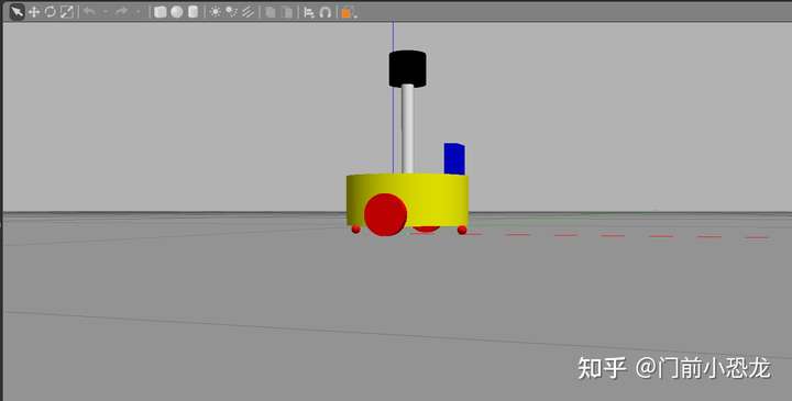
四、Gazebo仿真环境搭建
到目前为止,我们已经可以将机器人模型显示在 Gazebo 之中了,但是当前默认情况下,在 Gazebo 中机器人模型是在 empty world 中,并没有类似于房间、家具、道路、树木... 之类的仿真物,如何在 Gazebo 中创建仿真环境呢?
Gazebo 中创建仿真实现方式有两种:
- 方式1: 直接添加内置组件创建仿真环境
- 方式2: 手动绘制仿真环境(更为灵活)
也还可以直接下载使用官方或第三方提高的仿真环境插件。
1、添加内置组件创建仿真环境
首先下载模型:https://github.com/zx595306686/sim_demo.git
新建文件夹:urdf02_gazebo ---> worlds ---> box_house.world
新建launch文件:demo03_env.launch,写入以下代码:
<launch>
    <!-- 将 Urdf 文件的内容加载到参数服务器 -->
    <param name="robot_description" command="$(find xacro)/xacro $(find urdf02_gazebo)/xacro/car.urdf.xacro" />
    <!-- 启动 gazebo -->
    <include file="$(find gazebo_ros)/launch/empty_world.launch">
        <arg name="world_name" value="$(find urdf02_gazebo)/worlds/box_house.world" />
    </include>

    <!-- 在 gazebo 中显示机器人模型 -->
    <node pkg="gazebo_ros" type="spawn_model" name="model" args="-urdf -model mycar -param robot_description"  />
</launch>
运行launch文件:
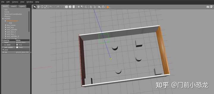
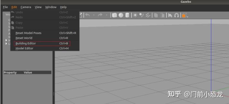
2、自定义仿真环境
启动 gazebo 打开构建面板,绘制仿真环境
保存构建的环境:
点击: 左上角 file ---> Save (保存路径功能包下的: models)
然后 file ---> Exit Building Editor
保存为 world 文件
3、使用官方提供的插件
官方模型库:git clone https://github.com/osrf/gazebo_models
将得到的gazebo_models文件夹内容复制到 /usr/share/gazebo-*/models
重启 Gazebo,选择左侧菜单栏的 insert 可以选择并插入相关道具了
参考:

评论(0)
您还未登录,请登录后发表或查看评论